Pointing out that smart control programs deployed via BMS deliver superior VAV performance and efficiency, Vijay Kumar adopts a hands-on approach to make a case for pressure-independent VAV.
– Vijay Kumar

Vijay Kumar
The Middle East HVAC industry has extensively used Variable Air Volume (VAV) terminal units for the past two decades. Initially popularised in low-rise residential units, pressure-dependent (by-pass type) VAV boxes were seen as a cost-effective solution compared to DX units. Over time, the more sophisticated pressure-independent VAV boxes replaced fan-coil units in high-rise multi-tenant buildings, facilitating easy retrofit to suit customer requirements. The sheer number of VAV box manufacturers across the region bears testimony to its widespread popularity.
This article specifically deals with pressure-independent VAV, and describes how a smart control program can overcome performance problems. When deployed via Building Management Systems (BMS), such smart control programs deliver superior VAV performance and efficiency.

Let us begin with some established facts – the pressure-independent VAV box is only as sophisticated as the electronic controller that controls it. And the electronic controller is only as sophisticated as the software control program that resides in it. The VAV box must be integrated into a VAV system; only then does its true performance show up. The crux of the performance problems arises due to different fit-out contractors working for different tenants, where their VAV boxes’ integration with the building’s overall VAV system gets easily overlooked. This results in VAV boxes fighting each other and “starving” the very zones they were designed to satisfy. As tenants move in and out of buildings, retrofit becomes a continuous process, which means their VAV box integration with building’s VAV system must also become a continuous process. This process, known as VAV Test & Balance, is where the BMS can play a major role, using the smart VAV control programs.

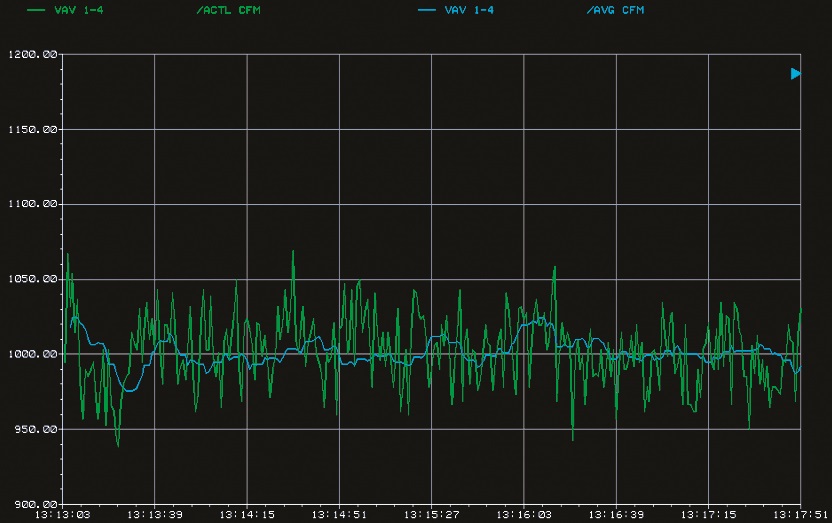
Duct Air-Flow Signal Noise; Blue graph is actual air-flow; Green graph is signal with noise error.
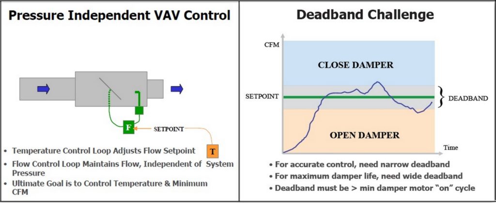
Several issues are addressed by VAV Test & Balance process. One of this is the deadband challenge, which deals with the sensitivity of control and its effect on damper motor life. Both are mutually exclusive, as a lower deadband is desirable to maintain comfort, whereas, it contributes to faster damper motor wear-out.
Another issue that’s seldom discussed is duct air turbulence, which creeps into the VAV system as tenant retrofit activity picks up. This causes air-flow signal noise, which impacts the accuracy of VAV box control. The air-flow graph diagram below shows a scenario, where a significant error (green graph) has crept into the control system through signal noise from duct turbulence. This noise is also caused by residual airflow in the ducts, even when all VAV boxes and associated supply air-handling units (AHUs) are shut off.

Non-Linear Damper Performance; Classic S-shaped curve nature of air-flow through non-linear dampers.
Finally, and probably the most challenging, is the non-linear output of VAV box dampers. The mechanical design of dampers results in a classic S-shaped curve, where air-flow change is sluggish at the upper and lower 20% of damper operation and, hence, difficult to control.
These complex challenges can be addressed collectively by using the smart VAV control program, of course, recognising the fact that it involves recommissioning the entire VAV system, that is, commissioning of not just a single VAV box but also all other “sibling” VAV boxes connected to a common “parent” supply AHU.

Duct Air-Flow Signal After Noise Elimination; Actual air-flow signal after noise elimination and calibrated zero.
First, let us look at how to eliminate the noise resulting from duct air turbulence. Command the supply AHU fan and its supply air damper “OFF”, followed by a “CLOSE” global command to all sibling VAV box dampers on that chain. Use a mechanical flow hood at each VAV box outlet and take three separate airflow readings at three-minute intervals. Average these readings and set this as calibrated zero air-flow for that VAV box. This is an important step, often ignored due to the misconception that VAV controllers are factory-calibrated. Remember that factory calibration only involves setting the minimum and maximum CFM setting for each VAV box, not the calibrated zero, which can only be done at site.

Slope-Based Air-Flow Control; The sensitivity of control depends on the slope of the damper curve.
Next, address the deadband challenge. Standard VAV control programs only employ Proportional and Integral (PI) logic, but that is more suited to linear low control loops. Instead, have the control program use a slope-based air-flow control approach, as seen in the graph ‘Slope-based air-flow control’. Run the damper for short bursts, say one, five or 10 seconds, and take the CFM reading at the low-end of the range, mid-range and the high-end of the range. Capture these readings on a trend graph, then calculate the slope to infer the anticipated air-flow at various positions of the damper.
In essence, the VAV damper motor will now know when NOT to over-control, and it will not try to overcompensate at the lower- and upper-end of the range. Rather than wait for a feedback signal to make further corrections to damper position (typical in standard PI logic), this smart VAV control program will use adaptive control from its learning of how much CFM will be delivered, at which position of the damper. This effectively eliminates the deadband problem and results in longer damper motor life, perhaps far beyond the manufacturer’s warranty period.

4-Step Sequence To Smart VAV Control
Finally, let’s look at the non-linear damper control problem. This is partly addressed above, using the slope-based approach. However, what is yet to be addressed is how to respond to major changes, say, when an occupant adjusts the thermostat controlling the VAV. The smart VAV control program translates the temperature set-point change in terms of CFM required to satisfy the zone, then makes the initial damper adjustment, calculates the slope of the graph, as seen in the diagram, and then uses the slope value to predict if a second adjustment is required to reach the set-point. If so, for how long to run the motor is correlated with the minimum motor run-time value specified by the manufacturer.
This effectively means a maximum of two damper movements to arrive at the set-point, rather than continuous adjustments to motor using traditional VAV control programs. No wonder then that smart VAV control programs are the way to go, to deliver better efficiency and longer equipment life under ever-changing indoor conditions.
CPI Industry accepts no liability for the views or opinions expressed in this column, or for the consequences of any actions taken on the basis of the information provided here.
Vijay Kumar is President, International Business, Cylon Controls. He can be contacted at vijay.kumar@cylon.com.
Copyright © 2006-2025 - CPI Industry. All rights reserved.