Saturday, 05 April 2025
Exponential development of high-rises the world over is posing challenges to design of efficient water distribution systems, says Ronak Monga
Driven by an increase in density of population, urban cities the world over are seeing an increase in construction of high-rise buildings. We are witness to an exponential vertical development of structures, which in turn, poses a challenge when it comes to design of efficient water distribution systems in them.
When deciding the water distribution and pumping strategy, it’s important to have a holistic view on the entire life cycle cost (LCC) of such systems. This article delves more on the various system layouts that are practically suitable for water distribution in high-rise buildings, indicating their merits and demerits, as well as comparing their LCC. Let’s first look at some of the critical considerations in pressure boosting systems…
Water delivered at fixtures – such as showers and taps – should be at a minimum pressure of 1.5-2 bar to ensure comfort for the end-user. The higher permissible limit of the pressure on most of these fixtures is 5-6 bar. A standing height of around 30 metres – that is, 6-8 floors – can add 3 bar static pressure to the lowest level. In a single zone 30-metre-height, wherein pumps maintain a pressure of 2 bar at the highest floor, the pressure at the lowest level in the zone will be 5 bar. Therefore, in a high-rise building, the zone needs to be formed after every 30 metres, or so, height.

Ronak Monga
Pressure-reducing valves play a key role in high-rise buildings. The flow to each 30-metre zone from the main riser passes through a pressure-reducing valve, so that pressure at the highest level in the zone is limited to 2 bar.
However, there are some disadvantages when using PRVs:
Hence, it is important to consider different system layouts to evaluate which system would fit best for any building or system type. Which layout to choose depends on several factors and the specific building design task in question – for example, local legislation and traditions, flexibility requirements or the possibility for future expansions. Any one system layout is not ideal for all scenarii.
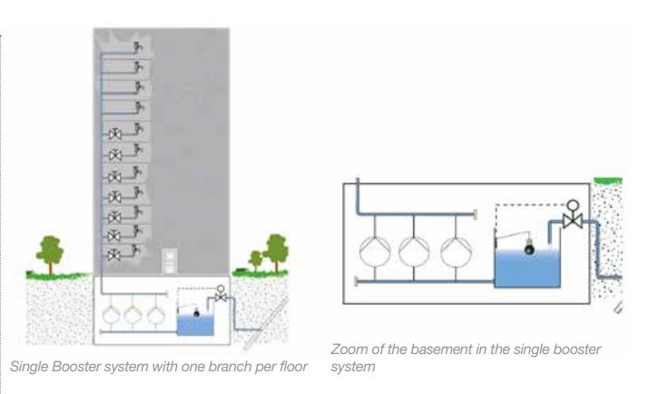
SINGLE BOOSTER SYSTEM
A single booster system is the simplest booster system available. It relies on a single set of pumps supplying pressure boosting from the basement to the point farthest away from the booster system. Such systems may be configured with or without initial break tanks. A water tank is placed in front of the pump system and filled with water from the mains. This allows the capacity of the mains to be lower than the building’s peak demand, ensuring constant pressure even in peak flow situations. The break tank is filled with water during low consumption periods and always ensures a uniform water supply to the booster pumps.
The advantages are:
The disadvantages are:
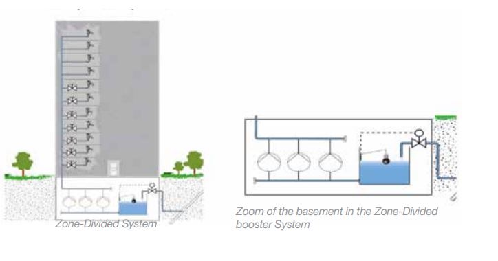
ZONE-DIVIDED BOOSTER SYSTEM
The building is divided into pressure zones of 10 floors or less, with a booster supplying each zone from the basement through dedicated risers. The supply system is split into several zones supplying a maximum of 12 floors each (approximately 40-50m static). This ensures adequate water pressure on all floors without using pressure relief valves. The minimum pressure on the upper floor in each zone is kept at 1.5-2 bar. The maximum pressure on the lowest floor in each zone does not exceed 4-4.5 bar.
The advantages are:
The disadvantages are:
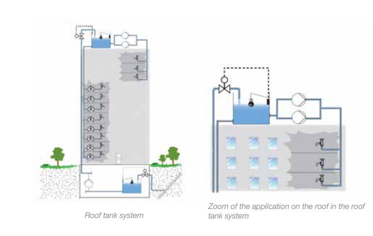
SYSTEM WITH ROOF TANK (OVERHEAD TANK) WITH ROOF TOP BOOSTER SYSTEM
Overhead tank systems use a transfer pump in the basement to fill the overhead tank by a level switch-operated control. Roof tanks ensure water pressure as well as water supply, in case of power failure. This solution requires pressure-reduction valves on each floor to avoid undesired high static pressures at the tap, which creates unacceptable noise while tapping. In this model, the upper six floors require a separate booster system to create sufficient pressure. The static pressure there is too low due to the insufficient geometric height to the roof tank.
The advantages are:
The disadvantages are:
SERIES-CONNECTED SYSTEMS WITH INTERMEDIATE BREAK TANKS
Series-connected systems with intermediate break tanks draw on several other systems, utilising centrally placed break tanks to supply both the taps in their own boosting zone and all the zones above. With this system, a building is divided into smaller and more manageable pressure zones of 12 floors each. Every zone is then served by its own booster set.
No pressure-reduction valves are required, and in case of electrical breakdown the tanks will be able to supply pressure and water for up to 12 hours. However, the tanks take up valuable space within the building, reducing the room available for revenue generation.
The advantages are:
The disadvantages are:
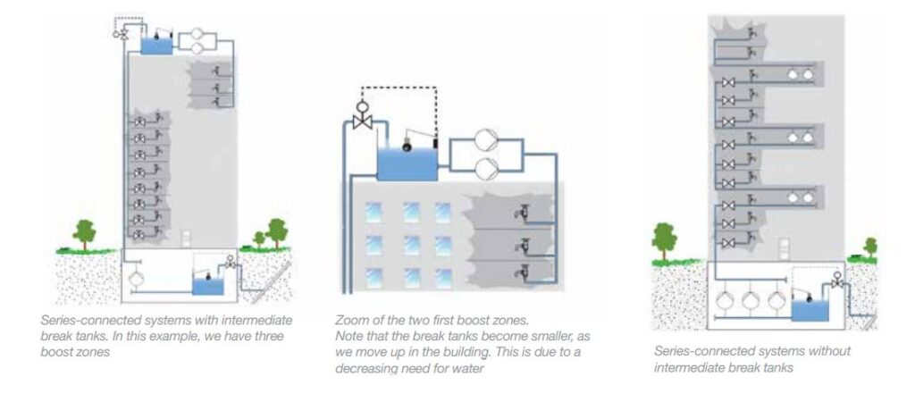
SERIES-CONNECTED SYSTEMS WITHOUT INTERMEDIATE BREAK TANKS
A series-connected system operates on the same principles as the previous system, but without the intermediate break tanks. This enables an effective usage of power, because the water is only pumped to the zone where it is used and does not go past it. However, complete control is particularly important.
When a consumer draws water on the upper floors, the booster systems must deliver the water from the bottom of the building.
The advantages are:
The disadvantages are:
LIFE CYCLE COST – LOOKING AT THE COMPLETE PICTURE
Life cycle cost calculations for pumping systems are normally conducted with only three parameters considered.
These observable costs are:
But more elements need to be considered, to ensure we are looking at the complete picture. In high-rise buildings, capital costs for piping, valves and tanks often exceed the costs for boosters many times over. In terms of maintenance cost, the cost to maintain roof tanks and break tanks exceeds any other cost of maintenance, even including pumps.
In terms of energy costs, the more we can avoid over-pumping, or pumping beyond required capacity, the more the savings are available.
As real estate becomes more valuable, the amount of saleable area gets increasingly important. In many instances, it is profitable to extend the height of a building. Another and more effective way to increase the saleable area is to reduce “wasted” space for building services.
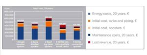
LCC = Cib + Cip + Cm + Ce + Cr
LCC = Life cycle cost
Cib = Initial cost for booster sets
Cip = Initial costs for piping, pressure reduction valves and tanks.
Cm = Maintenance costs
Ce = Energy costs
Cr = Lost revenue costs
Representative LCC comparison for a 25-storey building, above, shows that what might appear to be a good strategy up front, based simply on initial cost of booster pump sets, energy and maintenance costs, may represent a different result when a complete LCC is conducted; and hence, it’s indeed crucial to look at a total and complete picture.
Ronak Monga is Lead Business Development Manager for Commercial Building Services (Grundfos Gulf Distribution). He may be contacted at rmonga@grundfos.com.


")


Copyright © 2006-2025 - CPI Industry. All rights reserved.