Grooved-end mechanical piping systems reduce the mechanical room footprint, enhance system performance and save time and cost on installation, says Kris Holvoet, Product Engineer at Victaulic.
Grooved-end mechanical piping systems reduce the mechanical room footprint, enhance system performance and save time and cost on installation, says Kris Holvoet, Product Engineer at Victaulic.

Controlling costs and compressing schedules without sacrificing quality are key concerns for contractors responsible for mechanical room installations. Clients look for on-time, on-budget delivery of high-quality systems that work well and are easy to maintain. Alongside these drivers, space is becoming a critical factor.
The high cost of commercial and industrial building space and its scarcity has led to a growing trend to squeeze the size of mechanical rooms. Ever-tighter architectural designs for new builds are putting pressure on consulting engineers and contractors to deliver reliable, cost-effective HVAC solutions that keep the mechanical room footprint to a minimum. Similar demands are being made for mechanical room retrofits within the structural constraints of older buildings.
Grooved-end mechanical piping systems address all these issues. The lighter weight, smaller size, yet higher integral strength of grooved components compared with welded or flanged systems, make them ideal for projects that are tight on space or where mechanical rooms are located on higher-level floors. Their ease and speed of installation offer savings on total installed costs and they also deliver improved performance and reliability.
ELIMINATING RUBBER BELLOWS
Grooved couplings are designed with an elastomeric gasket contained inside the internal cavity of a ductile iron or stainless steel housing and secured by two nuts and bolts to create a leak-tight joint. This unique design gives the couplings noise- and vibration-reducing properties superior to those of traditional devices.

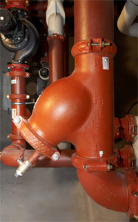
A suction diffuser enables pipework to be connected closer to the pump, permitting a smaller mechanical room footprint.
In traditional mechanical room set-ups, rubber bellows, or compensators, are placed in the piping system at either side of the pump to reduce noise and vibration and are sometimes used to correct misalignment between welded pipe and equipment, placing the rubber under intense stress in a certain plane. Not only do they take up valuable plantroom space, but rubber bellows are also considered the weakest point of an installation and the first component that is likely to fail, as general wear and tear, along with exposure to UV light in the mechanical room, causes the rubber to erode. They also require ongoing maintenance: as bolts gradually slacken and the system starts to weep, the bolts need to be tightened regularly. With a best life expectancy of 10 years, rubber bellows may need to be replaced several times within the life of the system, which involves system downtime plus the cost of a new unit. Failure of the rubber bellows can be sudden and unpredictable, causing serious health and safety risks if, for example, the rubber splits and water escapes.
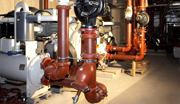
Installing three grooved flexible couplings on each side of a pump solves these problems. It eliminates the need for costly, bulky flanged units and avoids the use of rubber bellows. The coupling construction enables the gasket to seal against the pipe, while the metal housing provides both space for the resilient elastomeric material to flex, and containment to prevent overstretching. This creates a discontinuity similar to that of a rubber compensator. Additionally, ductile iron and stainless steel both have their own vibration dampening qualities, so the external housing also serves to absorb sound, thereby protecting equipment and enhancing the life time of the system.
A further advantage is removing the need for tie rods or the type of bracketry required to support pipework on top of and beneath bellows which increases time, labour and material costs. Special bracketry must either be prefabricated or fabricated on site and can account for around two thirds of the cost of installing a metre of pipe. Installations with flexible grooved couplings avoid these issues as they only require conventional brackets.
Three flexible couplings can be used not only with pumps but also with chiller units, cooling towers and any equipment with an engine that causes vibration. The use of additional grooved couplings – whether flexible or rigid – in the distribution lines will further reduce the transmission of vibration. By combining versatility with durability, the method provides a low-maintenance solution that saves space and delivers both practical and commercial benefits throughout the life of the system.
AVOIDING MISALIGNMENT
In addition to noise and vibration attenuation, grooved couplings allow for alignment ease in a pump installation. The pipe and system components can be fully rotated before tightening, without creating stress on the pump flange or equipment connection. Flexible couplings also help to accommodate slight deviation that might be caused if pipework has not been prefabricated to exact dimensions – something which is more difficult to achieve with a welded or flanged system.
IMPROVING PUMP EFFICIENCY
Cavitation is a problem frequently experienced, especially where space is limited. When turbulent water enters a pump chamber and the suction eye of a pump impeller, the degree of turbulence has a direct correlation with lower pump efficiency and greater hydraulic noise within the pump casing. To reduce the effects of turbulence before the water enters the centrifugal action of the pump impeller, suction pipes are typically kept as long and straight as possible before the connection onto the pump flange. Yet creating long lengths of pipe does not sit well with modern design trends which aim to keep mechanical rooms simple and compact.

A suction diffuser enables pipework to be connected closer to the pump, permitting a smaller mechanical room footprint.
Where a bend is connected directly onto the pump suction, the water flow may spin in opposite directions within the eye of the impeller. Pump energy, then, has to be spent correcting this action before producing the expected performance. Inevitably, both flow and pressure measurements will be less than those expected at the design stage. A simple alternative is to fit a type of strainer called a suction diffuser. A suction diffuser straightens out the spinning fluid created by the change in direction (bend) and enables pipework to be connected closer to the pump at a 90-degree angle. Eliminating long pipe runs, elbows and reducers makes for a smaller mechanical room footprint and optimum pump performance.
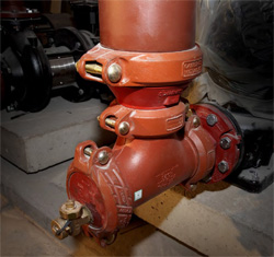
Designing mechanical rooms with grooved valves achieves similar space savings. Traditionally, check valves and butterfly valves need a spool piece between them to avoid damage to the valves. Having grooved check valves, close-coupled to grooved butterfly valves, eliminates the use of flanged spool pieces on the pump dressings and cuts out the need for flange adapters. Again, this reduces the mechanical room footprint. But space saving is not the only advantage: there are cost benefits too. When it comes to installation, avoiding an extra spool between valves means the job is completed more quickly so labour costs are reduced.
CUTTING LABOUR RISK
Driving down costs is a key objective for contractors. Whilst material costs are relatively easy to fix, labour costs are more volatile, leaving contractors open to significant labour risk on project costings. The grooved mechanical system reduces that risk by a large factor and competes favourably on total installed costs because a larger proportion of the total costs are fixed. When other joining methods are used, typically 70% of costs are subject to variation, making it difficult to estimate, which means a greater risk to the project budget. A grooved mechanical system with a quick and simple joining method and no need for jobsite preparation offers considerable cost-saving opportunities on installation.
Time spent on the jobsite is a critical cost factor, leading contractors to prefabricate as much as possible offsite. Prefabrication offers major productivity gains and labour efficiencies – especially when there is limited space on site. Creating a controlled working environment enables the optimum organisation of work and utilisation of skills, facilitating the highest standard of workmanship and reducing material waste. The grooved system lends itself to prefabrication, since pipes can be cut and grooved offsite and valves fitted to pump assemblies ready for final assembly in the field as needed. Working in such a way avoids the risk of loss or damage to components on the jobsite, whilst reduced material handling lowers the potential for accidents.
TIME SAVINGS

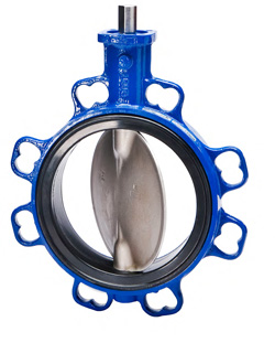
Butterfly valve
Ease and speed of installation are key benefits of grooved mechanical room installations, since just two nuts and bolts are needed to form a secure joint. Compared with the multiple nuts and bolts on a flanged strainer, depending on size, suction diffusers are up to three times faster to install. Once installed, the grooved system provides for quality control through visual confirmation of proper installation. Metal-to-metal bolt pad connection indicates that the joint is properly made and avoids time-consuming X-ray tests.
A system that uses grooved pipe-joining technology can be flushed out and cleaned in a fraction of the time needed for a system joined by other methods. When pieces of equipment need to be disconnected from the system – for instance, to avoid flushing dirty water through a chiller – this can be done quickly and simply. A temporary by-pass around a chiller that might take several days on a welded system can be avoided with the grooved system and the task completed in a few hours. When it comes to cleaning filters and strainers after flushing, access is much quicker and easier through the loosening of two nuts and bolts and the way the filter is positioned in the strainer makes is easy to extract. Modifications to pipework which may be required at any stage during the project can be completed with similar ease. Tasks such as changing out a filter or replacing a pump can be done in minutes rather than hours.
CONCLUSION
Switching from welded and flanged specifications to the grooved method for mechanical room installations can make a big difference to the success of a project. And its use is becoming more widespread. Because manufacturers of pumps and some other types of equipment have come to realise the advantages of grooved technology, many now offer a grooved outlet as a standard option. Not only does it make for easier product testing in the factory, but manufacturers know that having a grooved connection reduces the likelihood of additional forces on the equipment that could damage it.
Engineers, contractors and owners all stand to gain from grooved systems. Design engineers can realise space savings; contractors can make time and cost savings to achieve on-time, on-budget hand-over to the client; and owners get an efficient, reliable system which is easy to maintain.
The writer is Product Engineer at Victaulic
Get into the grooveGrooved-end pipe joining, or the “grooved” concept as it is known today, was invented in 1919 when the company now known as Victaulic designed the first mechanical pipe joint to successfully use a mechanical coupling combined with grooved pipe ends to join piping systems. Since being made commercially available in 1925 it has become a preferred joining method on many piping applications. A mechanical joint comprises four elements: grooved pipe, a gasket, a coupling housing, and nuts and bolts. The pipe groove is made by cold forming or machining a groove into the end of a pipe. The key section of the coupling housing engages the groove and the bolts and nuts are tightened with a socket wrench or impact wrench and hold the housing segments together. In the installed state, the coupling housing segments encase the gasket and engage the grooves around the circumference of the pipe to create a leak-tight seal in a self-restrained pipe joint. Couplings provide the convenience of a union at every joint and fall into two categories: flexible and rigid. Both provide the security of full circumferential engagement of the coupling into the groove for high pressure and end load performance. Rigidity is achieved with rigid couplings. The unique angled pad design provides positive clamping of the pipe to resist torsional and flexural loads. Flexible couplings allow controlled angular, linear and rotational movement, which accommodates pipeline deflection as well as thermal expansion and contraction. |
A contractor’s viewBriggs & Forrester MEP Division used the grooved system by Victaulic on the refurbishment of a large hotel in the UK where the building posed huge structural constraints and jobsite access problems. The project included a sub-basement mechanical room where the chillers and boilers were located. Vertical risers ran to mechanical rooms on the ground and first floors, and on the 11th floor another plantroom housed dry air coolers to supply the chillers with condenser water. “It was an extremely complex project with massive co-ordination issues to get things to fit within the available space,” said Bill Teasdale, Contracts Director at Briggs & Forrester MEP Division. Installers needed to work in confined spaces and the contractor had to be able to change things quickly as the project developed. Briggs & Forrester used no rubber bellows and no strainers around pumps and chillers but used flexible couplings and suction diffusers instead. Teasdale commented: “It made things much more compact and functional and it was easier to deal with single-source equipment rather than multiple manufacturers. Suction diffusers are a very good product which, during the commissioning process, really helped to keep flows through the pumps in straight lines rather than having cavitation issues that we normally experience in tight plantroom installations. Being able to close-couple valves made a huge difference and cut down time and labour. We directly employ a lot of our labour. So, having an opportunity to control costs is of major importance to our business.” The Briggs & Forrester design team produced 3-D drawings of the risers and all the mechanical rooms and gave them to the Victaulic Construction Piping Services (CPS) department. CPS drew up a bill of materials, sectioned off the job and used its “bag and tag” method to deliver everything as and when required for each section. “The Victaulic take-offs system worked very well. It’s definitely a system we’d want to use again. We may use the full CPS project management service on future projects.”
|
Copyright © 2006-2025 - CPI Industry. All rights reserved.