Monday, 03 March 2025
Positing the view that ice thermal storage is an ideal solution to improve the performance and efficiency of a district cooling plant, Georges Hoeterickx supports it with a case study.
Positing the view that ice thermal storage is an ideal solution to improve the performance and efficiency of a district cooling plant, Georges Hoeterickx supports it with a case study.
District cooling plant designers are continuously challenged to match the plant designs with different conflicting criteria, such as space, occupied area, power demand, plant efficiency, and last but not the least, the client’s budget.
An increasing number of designers of large central and district cooling plants consider the possibility of introducing ice thermal storage in their concepts, and depending on the benefits versus cost, decide to implement ice thermal storage in the cooling plant concept.
This was the case for the designers of the King Abdul Aziz University Central Utility Plant 2 in Jeddah, Kingdom of Saudi Arabia, a few years ago, when leading US and local designers were asked to design and build a new cooling plant to serve the University’s facilities having a total cooling, capacity of 158 MW.
A few of the specific design requirements were:
After in-depth investigations and evaluating various solutions, like chilled water storage, internal melt versus external melt, ice thermal storage and the use of eutectic solutions, the engineers and the university finally decided to implement ice thermal storage in the central plant’s concept.
The final solution selected was an ice thermal storage system, being the largest of its kind in the world, having a total ice thermal storage capacity of 445 MWh and providing a cooling capacity of 39 MW (melting ice only, excluding the chillers). In addition, the chillers would provide 158 MW cooling.
This cooling capacity was generated during 10 night hours by using 3,078 l/sec of 25% Ethylene Glycol solution (by weight). The average entering and leaving temperatures were –6.0 °C and –2.3°C, with an average chiller capacity during the night ice building mode of 44.5 MW.
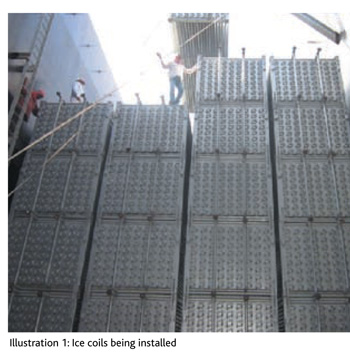
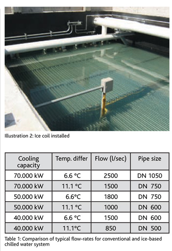
To accumulate the 445 MWh, a total number of 432 ice coils model IPCB 338 was needed. The 432 coils were installed in six individual tanks, each 20 metres in length, 8.7 metres in width and 12.2 metres in depth. The total required space to accumulate the 445 MWh was 12,860 m³ or 35 kWh per m³ tank volume. Illustration 1 shows the coils being installed in the tank and Illustration 2 shows the top of the ice storage tank filled with water ready to build ice.
By adding ice thermal storage in this project, the following cooling system enhancements, compared to a conventional central or district cooling plant system, were achieved:
With regard to the ice storage coils, the option to use elliptical tube design circuits was preferred, because this arrangement allows more kWh ice storage per m³ tank volume and more circuits (and surface) can be installed in a given tank width.
The ice thickness reached at the end of the ice build determined, in combination with the ice build time, the leaving glycol temperatures needed from the chiller during ice build. Therefore, the ice storage coil surface was adjusted to match the chiller capacities during ice build mode and at different lower glycol temperature conditions. This was even more important, as the chillers were of the centrifugal type and the heat rejection happened by means of radiators. This combination proved to be the most cost-effective and efficient method, considering the fact that due to lack of water, the use of open-type cooling towers for heat rejection was not an option.
The alternative solution with chilled water storage was not applied for the following reasons:
Conclusion
When considering all design aspects of a large central or district cooling system, very often, the integration of ice thermal storage offers unique opportunities to save initial and operating costs, while often other challenges are being taken care of.
The writer is Director of Business Development, Evapco Europe. He can be contacted at hoeterickx_g@evapco.be


Copyright © 2006-2025 - CPI Industry. All rights reserved.