Tuesday, 04 March 2025
Though VRFs have arguably stolen a march over other cooling systems, they still face some resistance due to piping leakage. Dharmesh Sawant demonstrates that this limitation can be eliminated by making certain modifications at the design stage.
Though VRFs have arguably stolen a march over other cooling systems, they still face some resistance due to piping leakage. Dharmesh Sawant demonstrates that this limitation can be eliminated by making certain modifications at the design stage.
Is there a paradigm shift in the DX market from conventional 1:1 ducted splits to VRF system? That is the question. Well, nobody knows the answer to it. But yes, VRF is definitely one of the preferred systems today for villas, low-rise buildings, mid-rise towers of up to 20 floors, schools, retail outlets and so on.
Why VRFs?
What is the reason for this shift? I see the following key factors:
Why not VRFs?
Now, let me focus on one particular application – villas – where we see this trend shifting to VRFs. However, the system has certain limitations, because of which it is facing resistance from conventional 1:1 units. One of them which I come across quite often is that in case of leakage in the piping, it leads to shutdown of the entire system. Fortunately, this can be easily addressed by implementing certain measures during the design stage.
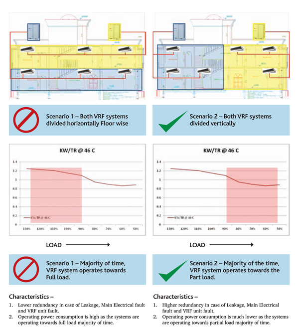
In case of villa application, it is usually observed that the entire ground floor is connected to one system and the first floor is connected to another system, as shown in Scenario 1 in the figure on the right-hand page. In case there is leakage in the piping system, it can lead to shut down of the entire floor. Just imagine the VRF system serving the ground floor being shut down due to leakage or some main power supply issues.
Overcoming limitations
This issue can be addressed during the design stage by carefully selecting a combination of indoor units to outdoor units. I usually recommend that consultants divide the two systems vertically instead of horizontally, as shown in Scenario 2 in the figure on the right-hand page. In other words, instead of connecting the entire ground floor to one system and the first floor to another system, it would be better to connect a few of the indoor units of the ground and first floor to one system and the remaining to another system.
The division of the indoor units can be achieved depending on the location of shafts to reduce the piping length. This gives higher redundancy in case of any leakage, issues in VRF or electrical faults.
This ensures cooling in some rooms on the ground floor connected with the other system.
Another advantage of dividing the system vertically is savings that can be accrued in the operating power consumption due to higher part-load efficiency. Now, how does it happen?
When the VRFs that are outdoors are divided floor-wise, due to application, it will run most of the time towards full load. For example, as shown in Scenario 1, the outdoor VRF unit serving the first floor bedrooms will be operational most of the time during night due to occupancy, and vice a versa for the ground floor.
Looking at the capacity simulation in case of a majority of VRF manufacturers, it is observed that VRFs that are outdoors have relatively lower KW/TR power consumption at part-load towards 50% load for the same design ambient temperature of 46°C, as shown on the right-hand page. Leading VRF players like LG, Mitsubishi and Toshiba are moving towards all inverter compressors. This makes part-load efficiency much better. For example, at 100% load, the KW/TR is 1.25 and at 50%, the KW/TR is 0.78 for the same ambient temperature of 46°C. Therefore, it always makes sense to combine the indoor units with the outdoor units in such a way that it operates towards partial load as shown in Scenario 2.
Scenario 2 will also help consultants to achieve higher credits from energy simulation because of lower annual energy consumption.
This is thus useful in the projects which are designed for Estidama 2 Pearl or LEED Gold or Platinum rating.
Conclusion
The conclusion of this study is that limitations of VRF systems can be eliminated by paying careful attention to details during the design stage. For this, I recommend that consultants liase with manufacturers regularly to be in the know about the best practices followed globally.
The writer is Senior Manager – B2B AC, LG Electronics Gulf FZE. He can be contacted at: dharmesh.sawant@ lge.com.


Copyright © 2006-2025 - CPI Industry. All rights reserved.