A question often asked by engineers is: Is a mechanical joint reliable? Rami Mahmoud , while answering it , addresses some of the misconceptions about them and makes a case for grooved pipe joining.
A question often asked by engineers is: Is a mechanical joint reliable? Rami Mahmoud , while answering it , addresses some of the misconceptions about them and makes a case for grooved pipe joining.
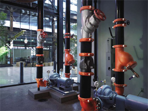 Grooved mechanical pipe joining is a no-flame joining technique of forming or cutting a groove in pipe ends and, then, joining them with bolted housings around a sealed gasket. The technology was deployed during World War I, as a fast and reliable way to get resources to frontline troops. Since being made commercially available in 1925 it has become a preferred joining method on many piping applications, when compared with welding, threading and flanging.
A mechanical joint comprises four elements: grooved pipe, a gasket, coupling housings, and a pair of nuts and bolts. The pipe groove is made by cold-forming or machining a groove into the end of a pipe. The key section of the coupling housings engages the groove. The bolts and nuts are tightened with a socket wrench or impact wrench and hold the housings together. The coupling housings engage in the groove around the circumference of the pipe and encase the gasket. A pressure responsive gasket, then, creates a seal unified joint that is enhanced when the system is pressurised.
The grooved method has gained widespread use in its 85-year history, but many myths and misunderstandings still exist. Why haven’t more eyes been opened to the benefits of grooved technology, which is versatile, economical and reliable?
For engineers, the benefits of the grooved system are many: the design versatility of the joint can allow both rigidity and flexibility, or a combination of the two, throughout a system when necessary; a mechanical joint provides noise and vibration attenuation, seismic relief, and accommodates for thermal expansion and contraction.
Added to these benefits, the system provides a union at every joint for ease of system maintenance and expansion. Perhaps the most important question for engineers will always be: Is a mechanical joint reliable? This article will explore some of the misunderstandings about grooved pipe joining, and remove any misconceptions about grooved joints weakening pipes, leading to premature failures or contributing to flow loss.
The basics of cut grooving and roll grooving
In terms of pipe preparation, there are often questions about how a groove is formed into the pipe and how that affects the pipe’s performance in different applications. There are two ways of grooving pipe: cut grooving and roll grooving.
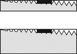
Cut grooving removes less metal, to less depth, than threading, thus maintaining pipe integrity.
Cut grooving is commonly used on pipes of standard or heavier wall thicknesses and for abrasive applications, where the inside of the pipe wall needs to be as smooth as possible to let materials pass without obstruction. Cut grooving involves the removal of a small fraction of pipe material in order to provide the necessary lip for engagement of the coupling housings. Cut grooving removes less metal, to less depth, than threading, thus maintaining the integrity of the pipe.
Cut grooving can be done manually or with a motorised tool. It is common practice to process a cut groove into plastic-coated or cement-lined pipe, as roll grooving may damage the internal coatings or linings of such pipe.
Roll grooving, the most common grooving method, is used on 90% of grooving applications today. Roll grooving was first used on a light or thin wall pipe, which had insufficient wall thickness for cut grooving. Today, roll grooving is used on a wide variety of pipe sizes and standard wall thicknesses, because it is a fast and clean technique. To create the groove, pipe material is radially displaced by a machine.
When grooving a pipe, pipe fitters place the pipe end between a roll set, and as the roll set is compressed and rotated, a groove is processed around the diameter of the pipe, recessed on the outside and protruding on the inside. The roll-grooving method can be used on carbon steel, stainless steel, copper and aluminium pipe or tubing as well as PVC pipe. Most coupling manufacturers will provide the proper roll grooving equipment based on customers’ requirements.
Latest technological developments include enhancements for medium to large diameter pipes that deliver greater strength and reliability through a robust coupling housing, deeper roll-grooves and increased coupling-to-pipe engagement.
Does grooving weaken the pipe end?
A question that is often asked regarding a grooved joint has to do with the reliability of the groove under stress.
When examining the stress on pipes created by internal pressure and the typical “overstress” failure mode, the cut groove has been shown to not be the weakest link. When under pressure, two basic stresses occur: longitudinal and hoop. Longitudinal stress is often described as “tensile” stress in material, the force pushing pipe apart in the axial direction. A failure due to longitudinal stress would cause a circumferential fracture around a pipe. Hoop stress can be described as ballooning or expansion of a pipe diameter in a radial manner. A failure due to hoop stress would cause the pipe to split lengthwise along its axis.
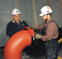
The latest grooved systems now offer even greater strength and reliability for medium to large diameter pipes.
Mathematically, the formulas for longitudinal and hoop stresses are shown below:
Hoop Stress = (Pressure x Outside Diameter) ÷ (2 x Wall Thickness)
Longitudinal Stress = (Pressure x Outside Diameter) ÷ (4 x Wall Thickness)
Therefore, in any given pipe diameter or pressure, hoop stress is twice the longitudinal stress. Analytically, this suggests that pipe failures due to overstress would show up as fractures along the length of pipe, such as weld-seam failures. Empirical or real world data confirms this to be the case.
Cut grooving reduces pipe wall thickness by removing a narrow circumferential strip of material on the outside surface. Hoop stress remains approximately the same since the groove is so narrow and is reinforced by the full wall thickness of the pipe on either side of the groove. The groove also is reinforced by the coupling key engaging the groove and preventing it from expanding diametrically. However, longitudinal stress will increase proportionally with the decrease in wall thickness. Therefore, if one half of the original wall thickness remains, longitudinal stress will be doubled or approximately equal to the hoop stress.
Since the cut groove depth in pipe with standard wall thickness is only about one-third the thickness of the original pipe, the hoop stress will remain larger than the longitudinal stress. Any “over-stress” failure will continue to occur along the length of the pipe and not at the groove, demonstrating that the groove area is not weaker than the longitudinal barrel of the pipe.
Cut grooving also does not create the stress risers that occur in threaded joints at the crests and roots of the threads.
With pipe that is roll-grooved, any potential increase in pipe hardness, reduction in tensile strength or reduction in elongation has no effect on the integrity of the joint, and pipe material changes are comparable to any other cold-forming manufacturing operations.
Flow dynamics
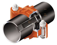
Coupling housings engage the groove and encase a pressure responsive gasket that creates a seal unified joint.
The inside protrusion or upset of a roll groove is small and smooth at its entry and exit and has been proven to have negligible effect on both flow and line pressure. Published ratings take into account the groove and, through testing on the performance of a joint, pressure ratings with a three-to-one safety factor are evaluated. However, some system designers and engineers still worry that the slight indentations will have a negative effect on the dynamics of system flow. However, published ratings take into account the groove and the testing on the performance of the joints’ established pressure ratings and safety factors.
Recent flow testing was conducted on the grooved joints; it confirmed excellent flow characteristics, with an insignificant contribution to system pressure loss. In fact, the amount was negligible in comparison with more common points of flow loss, such as pipe friction, valves, bends and branches.
Testing on grooved and plain end pipe, using 104.8mm Type “K” copper tubing and 50mm and 200mm Schedule 10 and Schedule 40 carbon steel pipe, saw pressure drops measured with velocities between 4 and 20 metres per second at ambient water temperature.
The results proved that pressure loss was negligible. These finding are also supported through rigorous independent testing by Factory Mutual Research Corporation, further attesting to the low-flow loss characteristics of grooved joints. These published qualifications are recognised globally and support the idea that the flow loss characteristics of grooved piping do not lead to extra operational energy costs.
Proven reliability
When it comes to specification of systems, as noted above, often every engineer’s final question is about reliability.
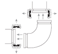
Grooved piping systems have a union at every joint for flexibility and ease of maintenance.
Mechanical grooved pipe joining has been proven through research, testing and extensive evaluation. It has stood the test of time in some of the most impressive engineering feats of the past century, including the Hoover Dam in the United States, the Grand Arche de La Defence in France, the Alexandria Library in Egypt, the Burj Khalifa in the United Arab Emirates and the Taipei Financial Center in Taiwan.
Moreover, mechanical joining has been a reliable and rugged component of mission critical applications, such as data centres, flammable chemical cleaning applications, the rigorous system demands required for high pressure applications in mines, power applications, life safety systems, tunnelling and in hydraulic elevators.
The benefits of grooving are verified by independent approval agencies worldwide, including Bureau Veritas (BV), Det Norske Veritas (DNV), Deutsche Vereingung des Gas-und Wasserfaches e.V. (DVGW), and the American Society of Mechanical Engineers (ASME. These are the same agencies that recognise welded, flanged and threaded systems and set forth the stringent requirements they must meet.
Conclusion
Engineers can be assured that grooved technology has been robustly tested by Research and Development Engineers in the lab as well as in the field to consistently demonstrate its strength and reliability. Details about the grooving process, the strength of grooved pipe and the flow characteristics are further explained in published reports from independent agencies.
The writer is the Regional Manager at Victaulic
Copyright © 2006-2025 - CPI Industry. All rights reserved.