Energy efficiency, initial investment and operation costs are key factors every plant designer has to deal with. While the first affects the environment, all three affect the bottom line.
Energy efficiency, initial investment and operation costs are key factors every plant designer has to deal with. While the first affects the environment, all three affect the bottom line. In this context, better design and appropriate components play a vital role in providing optimum results, and unpretentious valves, working behind the scenes, may help achieve the ideal, says Zulfiqar Mooraj.
As our demand for energy grows and operating costs increase, we are in continuous search of the most efficient system solutions at the lowest possible costs. Ideally, there is a line at which all the parameters meet. It is the meeting point of the optimised investment line, the line of total cost of ownership and the utopian bottom line that all are in search of. That said, at the end of the day, it is also about comfort – an area which no one really wants to have to compromise on.
Over centuries, the human race, in search of this comfort, has become more and more demanding and, consequently, put a lot of pressure on nature. Our needs and wants have depleted the Earth’s natural resources. The relationship between wants and needs has been disproportionately skewed in the direction of wants, taking a heavy toll on the environment. We, the engineering fraternity, carry a very high responsibility. In every field of work we come across opportunities where we can individually make a difference to society, the world, and the planet at large.
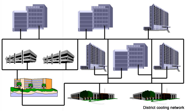
When it comes to sustainability, district cooling networks are generally regarded to have higher efficiency and lower per consumer cost of operation than standalone units or conventional air conditioning units. However, the system needs to be set up and components selected appropriately, so that we have the level of comfort we desire with a high level of efficiency and, consequently, a reduction in operating costs.

Hydraulic balancing is an important component of a district cooling plant and ensures that all consumer sub-circuits receive sufficient chilled water. In order to reduce capital and operating costs to a minimum, it is important to make sure that cooling systems operate at optimum efficiency, irrespective of the prevailing demand in an installation. Some important factors to achieve this are:
Energy efficiency can be achieved by selecting the appropriate components and instruments that are fine-tuned to provide optimum results.
It all begins with the selection of the appropriate pumps. Variable volume systems are common today.
Variable volume systems ensure high return temperatures even at partial loads. The transfer of energy is, therefore, more efficient. As flow volume increases, the transfer efficiency is reduced (depending upon the heat exchangers) and, hence, some loss of efficiency. Higher efficient heat exchangers can be used to reduce the losses. This, again, is a question of efficiency versus costs and it is the engineer’s responsibility to find the ideal point between investment costs and operating costs.
A pump running at 25% of its designed head with 50% of the design flow rate consumes 12.5% of the electrical power it would consume under design conditions.
Pump Power = pressure difference x flow rate / pump efficiency (P = ∆P/η)
Pressure difference decreases with flow rate2 (∆P decreases with Q2)
So power decreases with flow rate3, which leads to energy savings and, hence, cost savings
As mentioned earlier, hydraulic balancing is an important task in district cooling networks, as it ensures that all circuits that are fed by the system are balanced, resulting in all receiving the needed flow even at partial loads.
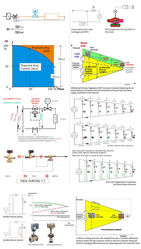
As temperature/flow control valves (FCVs) modulate from the fully open to the closed position, when there is no demand, the flow rates fluctuate from 100% to 0%. This results in an interaction between system and pump characteristics, which causes the differential pressures in the distribution network to vary, thereby creating complex hydraulic conditions. These have to be analysed and controlled, if one wishes to achieve predictable efficient operation of a system. This is achieved by the use of Differential Pressure Regulators (DPCVs).
Let’s consider a case where we have seven consumers in a circuit with different maximum demands.
The system is designed in such a way that the last consumer always gets sufficient flow. Flow control is achieved by the use of FCV. Maximum consumption is the sum of all the individual consumers. Depending upon the flow distribution and partial loads, the differential pressures will increase across the consumers, causing more than needed flow to the consumers closer to the chiller and, thereby, causing the consumer farther away to be deprived of it. This is balanced out by the use of Differential Pressure Regulators (DPCV) across each sub-circuit, for example, ETS.
Control Valve Authority is the term that is used to explain how much control the FCV has over the changing load situation. It needs to be noted that there is cost involved in high valve authority, while insufficient authority leads to instabilities. There is also a relationship between required valve and valve design/rangeability. Based on experience, most plant designers will aim for 50% authority.
Control Valve Authority is the relationship between the differential pressures across the control valve, when it is fully open to the differential pressure across the entire circuit. Hence the 50% ideal, put simply means that the pressure loss across the control valve should be equal to the pressure drop across the rest of the system. The main component in an ETS is the heat exchanger. Hence, selecting a valve whose differential pressure is equal to that of the heat exchanger will result in a 50% authority. Typically, the higher the valve authority, the better the control. However, this will result in higher operating costs due to pump head requirements.
The inclusion of differential pressure regulator helps reduce the operating costs and increase the system efficiency. DPCVs reduce the total pressure drop in the circuit by maintaining it to a set value and, thereby, increase the valve authority.
The minimum controllable flow rate is dependent upon the valve’s rangeability (valve design and type-dependent) and on the valve authority (system design-dependent).
If small loads need to be controlled, a low valve authority and low rangeability, in combination with the heat exchanger characteristic, could cause system stability problems. Higher valve authority requires more pump load and, hence, increases operating costs. So, it is a matter of finding the ideal midpoint, which plant operators and designers have come to agree upon as being between 20% and 50% (0.2 and 0.5) and approximately 50% (0.5) being most commonly planned for in systems for stable operation with most universally used valve designs.
Depending upon the rangeability of the selected valve, it may be possible to go towards the lower point and, thereby, reduce operating costs, but is often associated with an increase in installation costs. Most control valves have a rangeability of 30:1 or 50:1. Valves with a rangeability of over 50:1 will enable operation at lower valve authorities. A combination of the factors is used to calculate what is known as the installed rangeability. In the final analysis, the basic principle remains – the higher the authority, the better the control and more stable the operations and responses to changes in temperature/flow requirement.
Combined flow and differential pressure regulators (or pressure independent control valves – PICVs) have been developed to provide maximum control (Valve Authority = 1, ie, 100%) with a reduction in pressure loss compared to a solution with DPCV and FCV, giving valve authority of 0.5. The interesting aspect is that the investment cost is also reduced compared to the DPCV/FCV solution, all in all, resulting in efficiency increase as well as reducing the startup time at lower operating and investment costs. It goes without saying that as with all equipment, they need to be selected properly to give the best results.
Compare the cost of energy against the efficiency when using a PICV as compared to an MOV (FCV) with a DPCV.
As an example, consider the system with a flow rate of 10 m3/hr and a load with a differential pressure of 0.3 bar. This means that if we design for 0.5 authority, the valve would have to have a pressure drop of 0.3 bar, as well. Also, consider that the valves flow coefficient (Kvs) is the relationship between flowrate and square root of the differential pressure (Kvs = Q/√dP), which, for our example, would mean Kvs = 18.3. Kvs values are manufacturer-specific. If we assume the closest higher Kvs = 20, and we select the same, then the installed valve authority is 0.45 (45%). When fully open now, the valve would result in a pressure drop of 0.25. A differential pressure regulator with the same Kvs would affect a pressure drop of 0.25 and would have to be set at 0.55 bar (DPCV Set Point). Hence the total pressure loss in the system would be an addition of all 3 (DPCV + FCV + Load) pressure drops, resulting in a total system pressure loss of 0.8 bar.
Combined valves (PICVs) are designed in a way that they have constant pressure drop across the flow limiter. For our example cited, it would be 0.2 bar. The pressure drop for the valve would be the same, ie 0.25 bar. This results in a total pressure drop requirement for the PICV of 0.45. Taken together with the pressure drop of the load, the total system pressure drop is reduced to 0.75 bar, while the valve authority is increased to 1. This results in a saving of 0.05 bar per sub-circuit, and when accumulated over the system, will result in savings in operating and maintenance costs combined with reduction in capital costs and increased system efficiency.
Shorn of all the rhetoric, finally, energy efficiency is a matter of fine-tuned engineering, working quietly behind the scenes.
The writer is Managing Director, SAMSON Controls FZE. He can be contacted at: zmooraj@samson.ae

Copyright © 2006-2025 - CPI Industry. All rights reserved.